Okay mom, I don’t suggest that you read this blog entry :)
I seem to be talking about this subject a lot these days so I figured that it would be a good topic for my blog.
Now where do I begin?
Some may believe this is a very trivial topic.
Some may say that it’s not really even an issue worthy of mention.
Some may not even be aware that this problem exists.
Some simply don’t care and therefore make it someone else’s problem.
Well, I’m here to say that this IS a problem. …and it’s simple math … Geometry actually.
…and there are people who deal with this problem every day …and they shouldn’t have to. (Okay, I know those are strong words, but I’m a passionate sort of guy as you will come to find out.)
This subject isn’t new, but with the advent of computers and civil engineering software like InRoads, GeoPAK and Civil 3D, it has been brought more into to limelight. The root of the problem is encountered when working with geometry layout tables with 2 decimal coordinate and length accuracy. The problem itself is the struggle comparing layout coordinates on drawings and resolving the differences when preparing the project for construction staking.
More specifically the problem is one of using CAD graphics (MicroStation or AutoCAD) vs. layout from a geometry table vs. ‘reality’ (actual design) that constantly generate issues with curve and point layout during the staking process because the coordinate accuracy on the ‘paper’ tables cannot adequately recreate the design geometry when it was initially laid out with programs such as InRoads.
Let me illustrate this:
Illustration Creation:
-
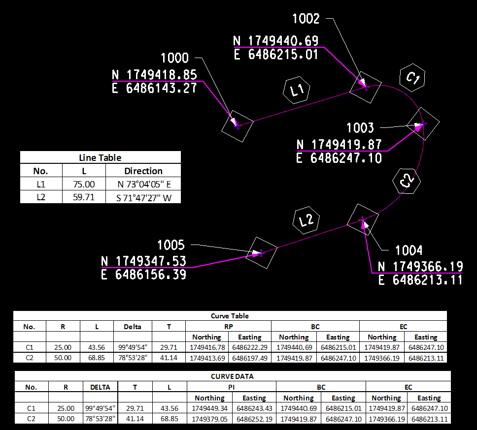
Using InRoads geometry tools, I’ve laid out a bull-nosed median with a compound radius.
This alignment was laid out by assuming two arbitrary tie-in points at the ends (Pt #1000 & 1005). Then the direction of the tangents, defined by some striping or layout reference was constructed. Finally, the compound curves were laid out based on the two required radii.
-
I’ve annotated coordinates at key points - use standard 2 place precision.
(Done with InRoads Place Plan Note)
-
I then created Line & Curve Tables - use standard 2 decimal precision values
(Done with InRoads View Horizontal Annotation)
The following information is present to show the actual layout, and describe the geometric details of this illustration.
Illustration Sample:
NOTE: All key points were stored using 2 decimal place accuracy for later reference and easier reconstruction.

Original Alignment Constructed: (2 place precision report)

Original Alignment Constructed: (4 place precision report)
And this is where the issues begin.
During the engineering layout of this alignment, more than likely, a bearing was used. Bearings, out to the seconds accuracy, produce a point location that has significant digits greater than two. If we look at a report of the sample alignment carried out to 4-places you will see this.

Alignment Reconstructed by Coordinate Emphasis:
Now, as is done time and time again in survey offices around the globe, let’s reconstruct this alignment using the coordinates found on the construction drawings. I’ve laid out the alignment starting with the first two decimal place coordinate. I continued reconstructing the alignment using the information in the tables. (With emphasis on mainly the coordinates on the tangent start / end)
What you see in blue was used during the reconstruction. What you see in yellow are the problem areas. The red boxes are noting the flags that InRoads sends up showing that the curves are non-tangent. You can see this by comparing the tangent direction of the linear portion against the tangent of the curve.

Alignment Reconstructed by Bearing Emphasis:
Let’s do this reconstruction another way.
Now I’ll lay out the alignment starting with the first stored 2 decimal place coordinate. And then reconstruct the alignment using the information in the tables again. But this time I’ll reconstruct it with emphasis on mainly the tangent bearings in order to maintain the tangency of the curves. I’ll also hold the radii and length of curves. (Of course there are other layout combinations as well.)
It’s better, but you’ll find that even this technique results in problems.

Conclusion:
There is simply no way to recreate the alignment and match all the information provided in the Curve / Line table. Something has to change.
-
The bearings and angles are accurate using DD.MM.SS
-
The coordinates are accurate at 2 decimal places
-
The bearing and angles are both precise
-
The distances and coordinates are also precise
The Issue:
The level of precision and accuracy between the coordinates and bearing / angles are incompatible. The bearing & angles are more precise than the coordinates and lengths; hence the difficulty during reconstruction of the alignment.
A Solution?
We have to determine the best way to address this issue so that Survey can input their stakeout lines with a predictable and consistent methodology that provides the appropriate field accuracy, while minimizing the amount of rework and decision making by the Construction Survey departments.
There is an easy solution.
If the engineers, during the layout of the project, are using some sort of Civil software such as InRoads, then the actual ‘engineered’ data file can be used by the survey group during construction.
Will this really solve the problem? Yes.
Will it be done? Probably not.
Fear.
Liability.
Responsibility.
Ownership.
Some people are reluctant to change. This reluctance will bring about the most amazing reasoning.
“We never had to do it in the past.” (Oh the glories of the “old days”. Wake up …they’re over.)
“More than 2 decimal place accuracy is over-kill.” (Then why use angular ‘seconds”?)
“It’s not engineering’s problem, let construction deal with it.” (How irresponsible is that?)
“We didn’t use computers in the past and things always worked out fine.” (Really!?! …then go back to the boards. …and good luck with that.)
I think the time is soon coming for a long talk about engineering evolution from the boards to computer.
Get with the program guys. You spent the money … now use it and leverage its strengths.
Until next time!